Explainer Video for Industrial Process
Trinity Animation produced a series of three corporate explainer videos for their client, the Metropolitan Council for Environmental Services (MCES). The MCES is responsible for the lion’s share of the public utilities serving the Twin Cities region. The first custom corporate explainer video was created to inform the public about the critical function of their wastewater incinerator system, called “The Metro Plant.” The Metro Plant is the system’s largest wastewater treatment plant responsible for treating up to 65% of the region’s wastewater.
The Metro Plant incinerates wastewater solids through an efficient thermal combustion process which diminishes solids by 95% and eliminates pathogens. Through 3D animation, Trinity artists have created a clear and detailed demonstration of the intricate process so the public can easily understand the workings of the Metro Plant.
The MCES provided Trinity artists with several assets needed to build these corporate explainer videos. The artists were first provided with a script which explained in detail what MCES envisioned. The MCES further provided Trinity artists with a complete 3D model of the entire plant which Trinity artists modified by applying textures, organizing mechanical elements and animating the motion of the overall process. Other imagery was used as reference material such as photographs, 3D imagery, and 2D illustrations of the plant displaying how the client wanted the corporate explainer video to unfold.
A. Incineration Process at The Metro Plant:
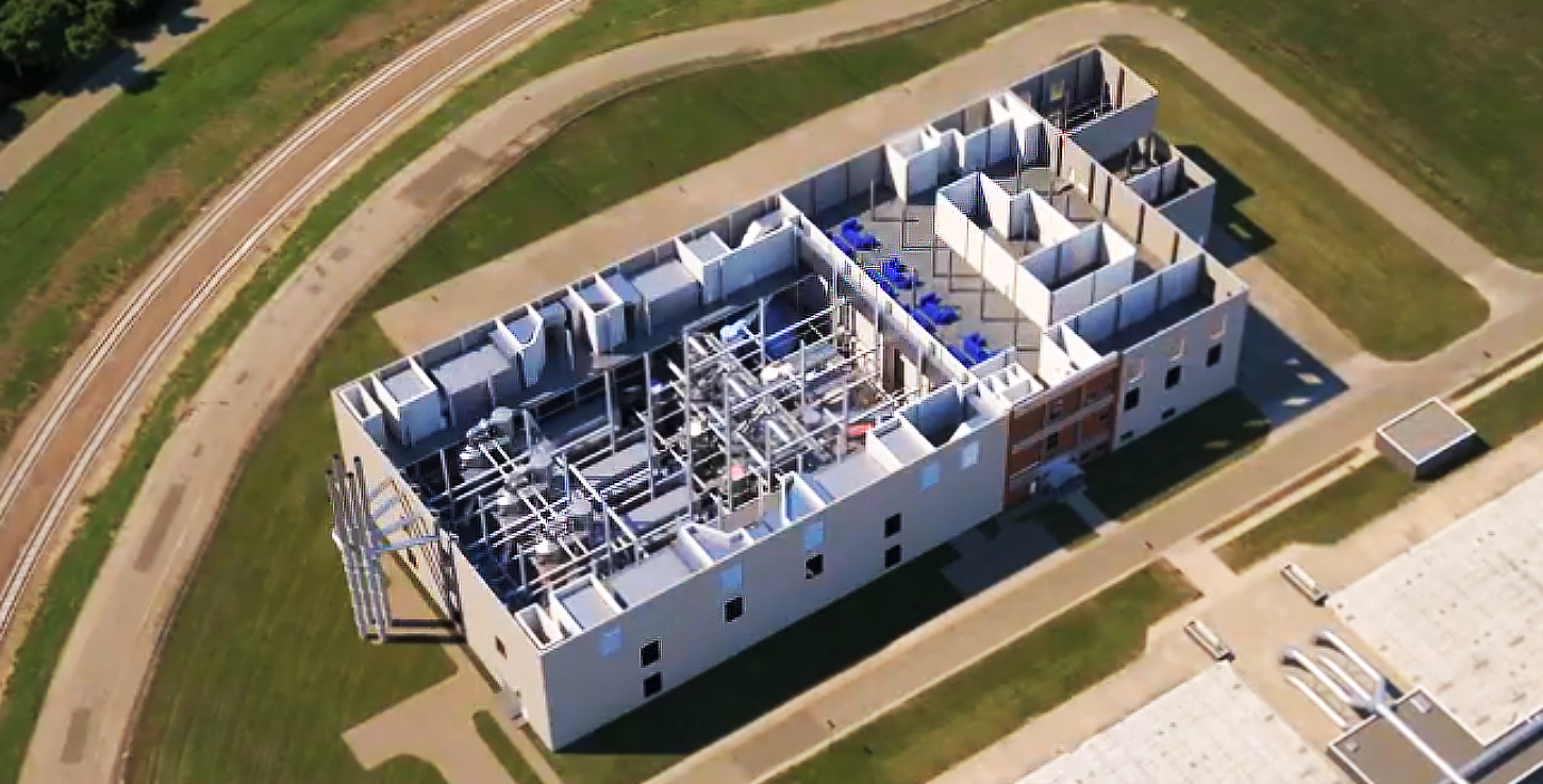
This corporate explainer video explains the incineration process at The Metro plant. Using the 3D model of the plant provided by MCES, Trinity artists began the animation with a bird’s eye view of the Metro Plant. The plant’s roof is then removed to allow viewers to see the intricate arrangement of the machinery inside the plant. The camera then swings about 180 degrees around the building and maneuvers to a ground level view. As this is happening, half of the plant disappears and a cross-section view of the machinery inside the plant is revealed. Lastly, the background fades to black so that the main focus is on the Plant. These custom visuals are essential when Trinity’s clients need to explain complicated concepts to the general public.
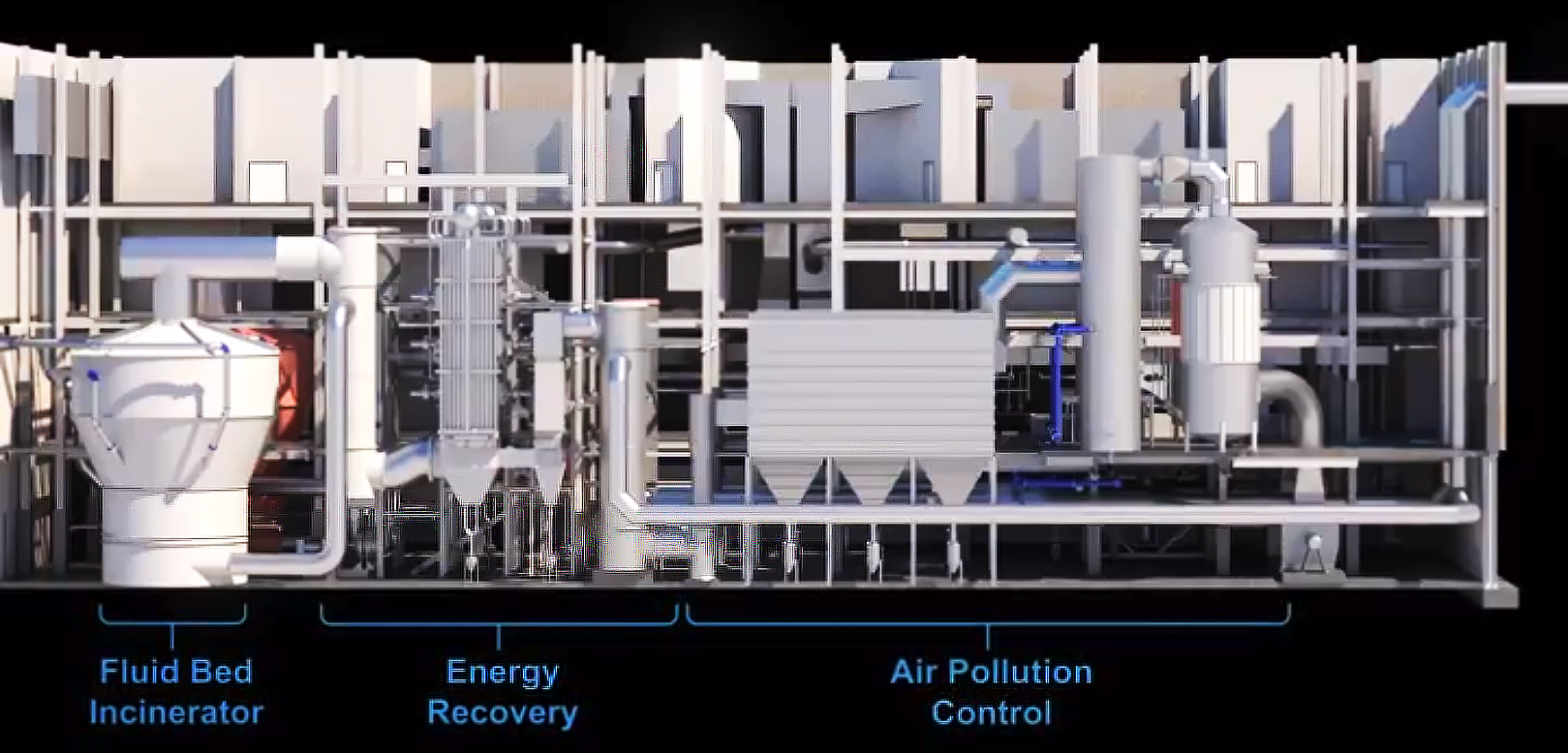
The 2D pie chart displayed in this animation was developed and animated by Trinity based on still images of a pie chart provided by MCES. The chart displays the percentage of solids reduced to ashes and resulting water vapor.
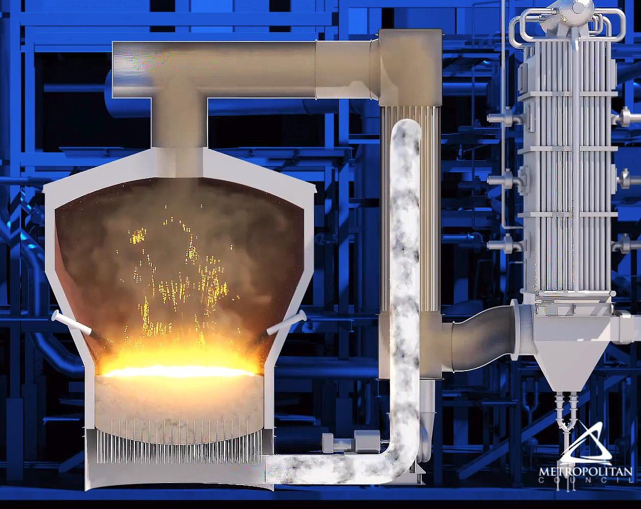
While displaying a cross-sectional view of the fluid bed incinerator, Trinity artists proceed to demonstrate the process of incineration. First, a bed of sand, which has specific granulated and chemical properties, fills the chamber of the fluid bed incinerator. Trinity artists then animate the air that flows through a pipe system and is distributed under the bed of sand, causing the sand to boil. Natural gas is then emitted into the chamber while the narrator explains the heating process of the chamber. Fire is impressively simulated by Trinity artists as it emits from both sides of the incinerator into the chamber. Biosolids are then fed into the fluid bed incinerator which combusts after reaching 1,375 degrees Fahrenheit. Bigger flames are animated inside of the chamber which releases what is known as flue gas, consisting of water vapor, carbon dioxide, and fine ash. Water particles are then displayed exiting the chamber through a pipe in the top of the incinerator for further treatment. In the final scene, three fluid bed incinerators are presented side by side.
B. Energy Recovery for Incineration at The Metro Plant:
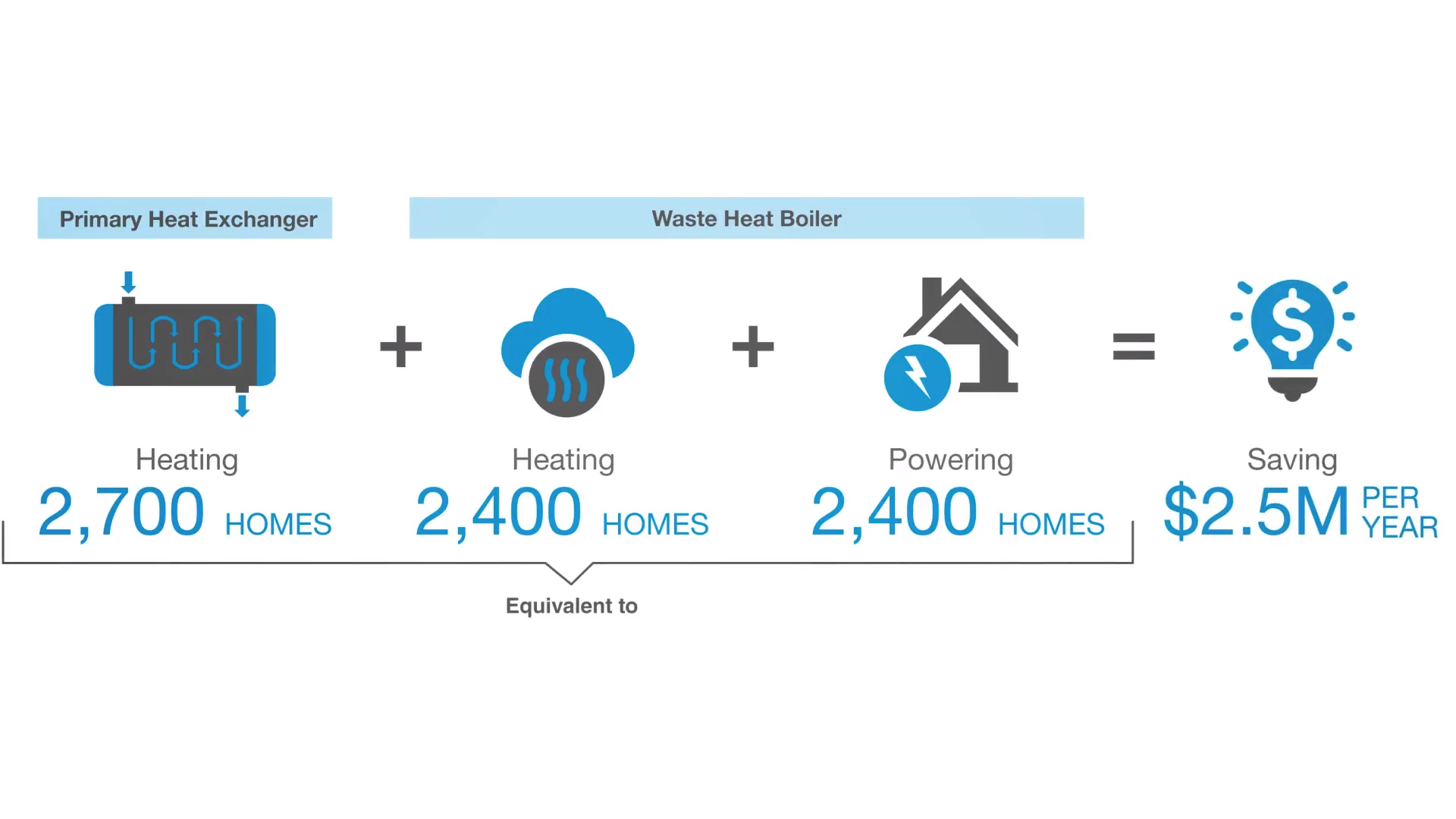
The second corporate explainer video in the series explains the energy recovery process at The Metro Plant. This corporate explainer video begins the same way as the last explainer video, with a bird’s eye view of the plant which transforms into a cross-sectional ground view of the plant. Another 2D graphic that The Metro Plant provided Trinity artists is brought to life through animation informing viewers about the financial benefits that the incinerating system provides.
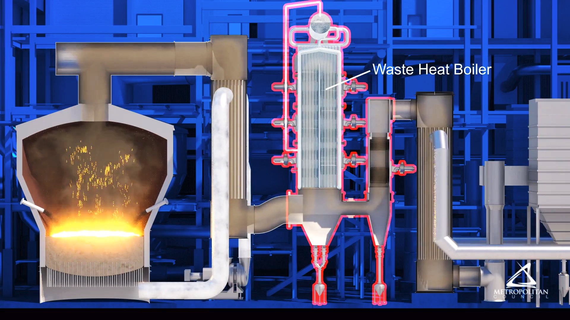
This cross-sectional view of The Metro plant displays several different machines than the last video including the fluid bed incinerator, waste heat boiler, and secondary heat exchanger. This corporate explainer video starts off where the last explainer video ended – with the recovered heat energy. Recovered heat energy is shown moving through the pipes where it reheats the combustion air for the fluid incinerator and reduces start-up fuel use. The narrator then explains how water in the waste heat boiler is reduced to steam which is used to heat plant buildings during the winter. Red outlines trace the edge of the machines through the demonstration so viewers have a clear understanding of which each machine does

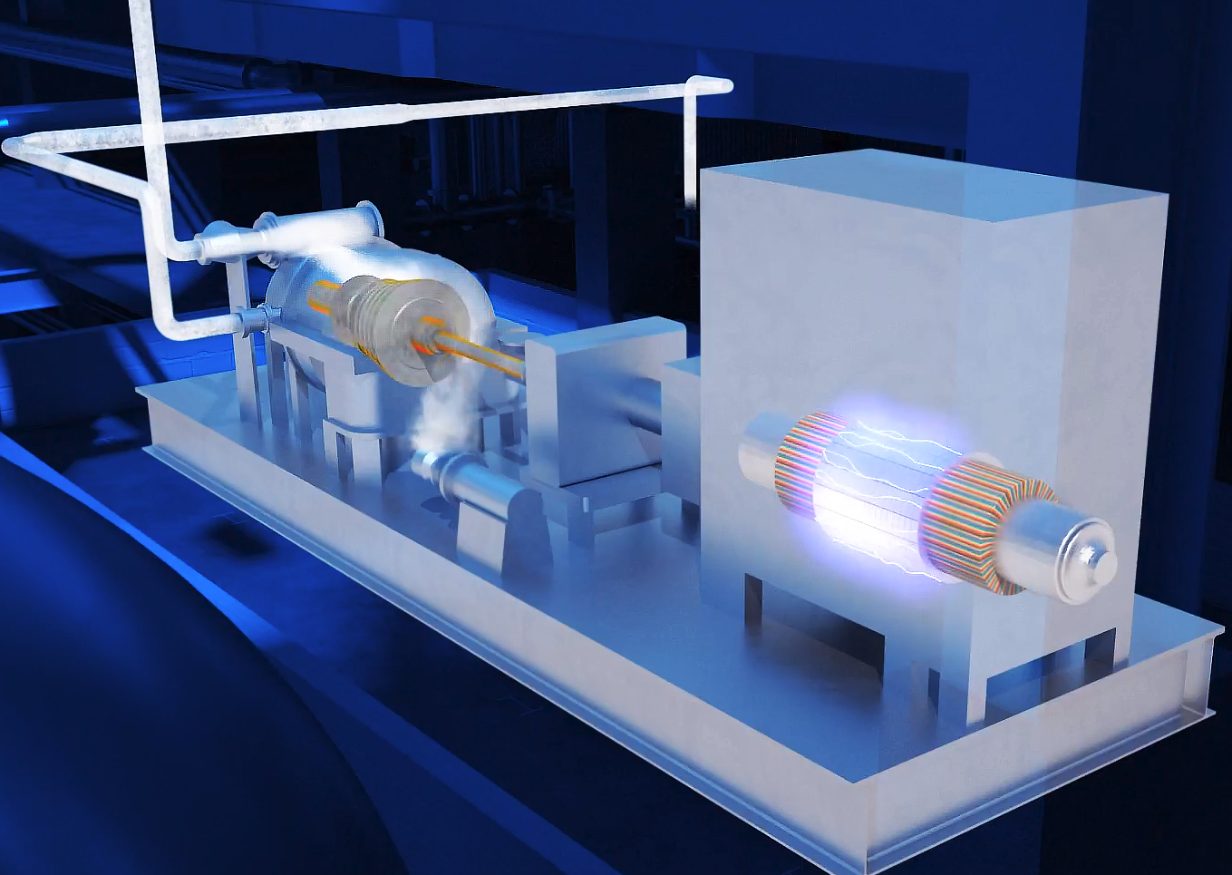
A close-up shot of a 3d rendered transparent turbine is then displayed allowing viewers to see the steam being converted into electricity. The corporate explainer video then draws the viewer’s attention back to the cross-sectional view of the fluid incinerator, waste heat boiler, and secondary heat exchanger where the recovered heat energy turns moisture to steam until there is no visible plume being emitted from the incinerator stacks.
C. Air Pollution Control for Incineration at The Metro Plant:
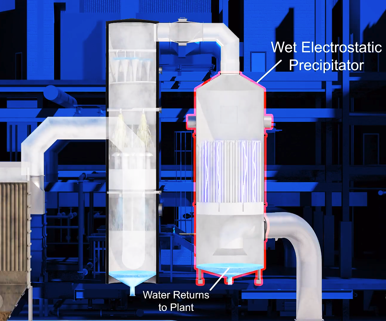
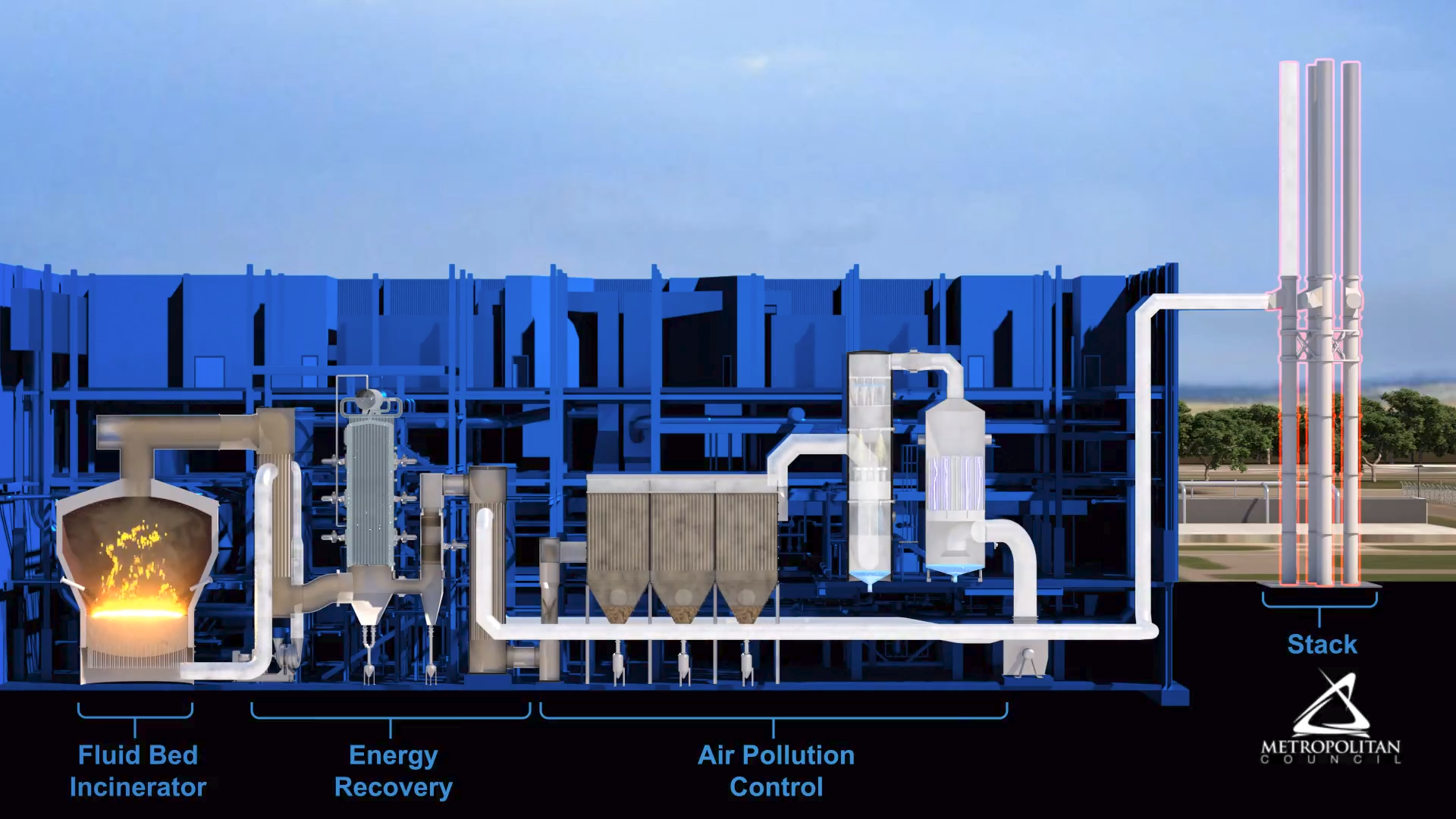
This third explainer video in the series demonstrates air pollution control over incineration process at The Metro Plant. It displays the same cross-sectional view of the machinery inside of the plant as the last two explainer videos, but goes further and provides background on the carbon tower, the baghouse, the wet scrubber, and wet electrostatic precipitator. The view shifts to each individual machine as it is discussed. Mercury is shown as it is eliminated in the carbon tower. The substance is then transferred to the baghouse which filters outs particulate and metals using cloth filter bags. Water vapor is shown flowing through the chambers until it transfers through the pipes to the wet scrubber. In the wet scrubber, water cooling sprays remove particulates and acid gases where a caustic solution is added when needed. Each of these materials are labeled with text and 2D graphics for the viewer. The water is then returned to the plant for treatment. After that, the wet electrostatic precipitator collects fine particles onto electrically charged tubes.
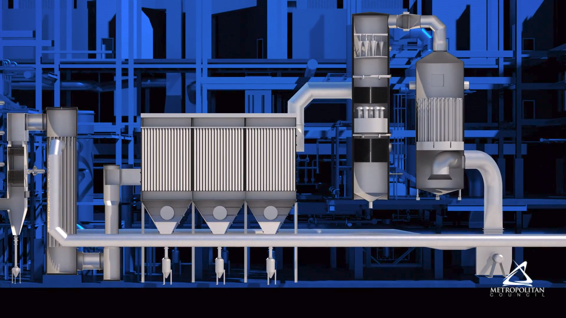
A zoomed out view of the cross-sectioned plant is then displayed revealing the plant stacks where the emissions are clean, colorless, odorless, and with no visible plume. All machines discussed in the videos are shown in action with realistically simulated fire, smoke, and water elements.
