SpillX Fuel system- CAD Animation
4 mins read

SpillX Fuel system- CAD Animation

Trinity Animation has created a striking CAD animation depicting a high efficiency locomotive refueling system for its client, SpillX.  Trinity’s CAD animation helped this innovative manufacturer explain the key features of its product to its business customer base.


This is a 3D rendered still image from the cad animation displaying a realistic representation of the SpillX fuel system nozzle being inserted into a locomotive. All elements are rendered with realistic textures through Trinity animator's 3D software. The locomotive is displayed in a vibrant red along with the SpillX fuel system nozzle.
This 3D rendered still image from the CAD animation displays a realistic representation of the SpillX fuel system nozzle being inserted into a locomotive, before diving into the interior details of how it operates.

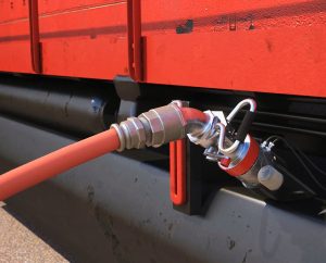
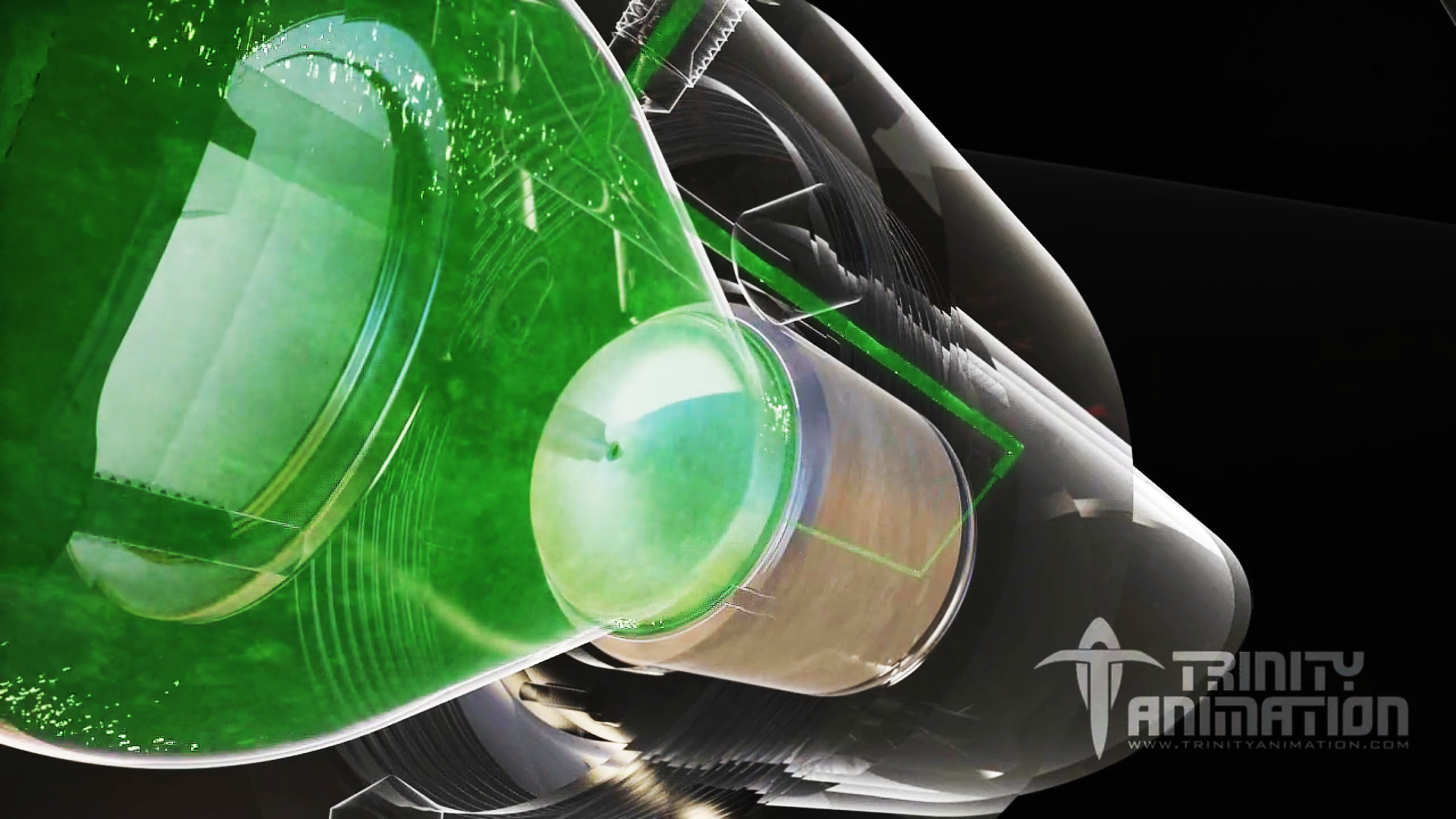
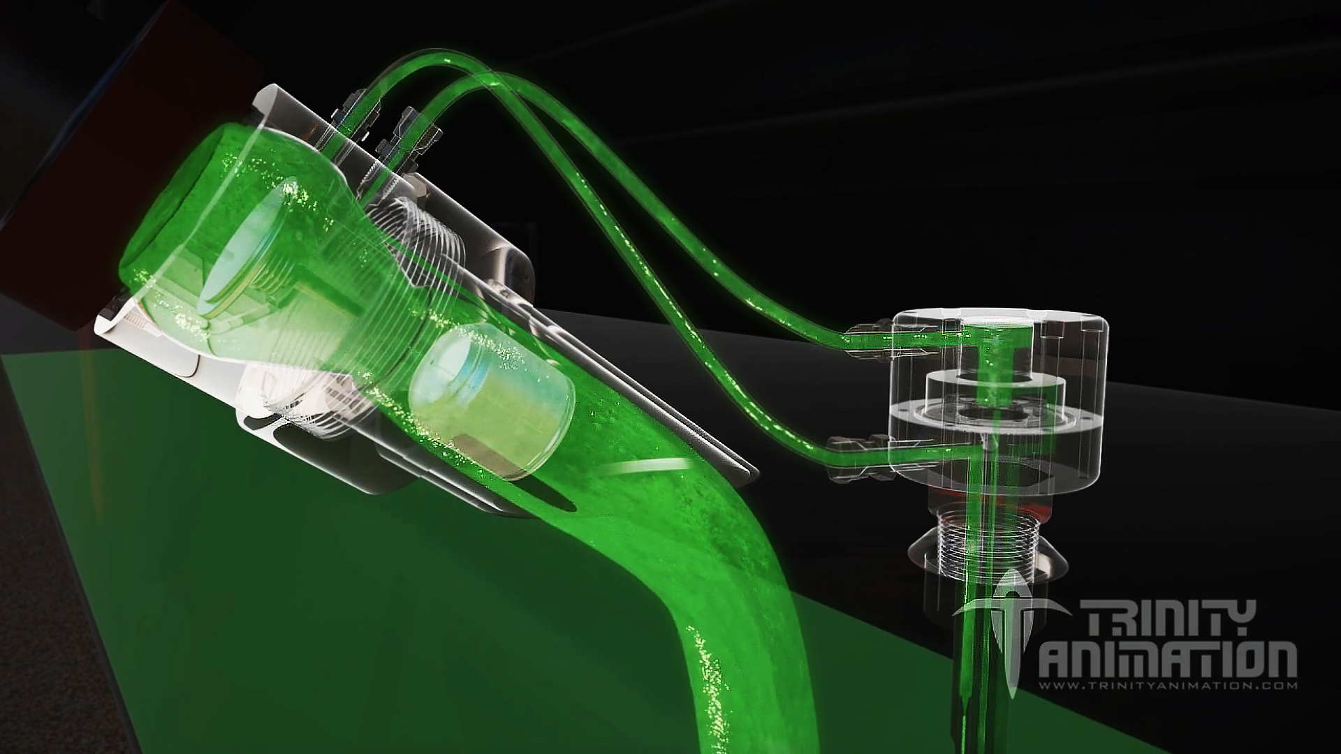
The innovation consists of an automatic shut-off system which prevents costly and hazardous fuel spills. The fueling system drew on technology developed in the aviation industry and applied it anew to the needs of the locomotive industry.  This CAD animation brings to life a  system that has the capacity to reach fueling rates up to 600 gallons per minute using a dry break connection which ensures no fuel at the point of disconnect.   The design of the locomotive fueling system began with tested aircraft fueling technology which was then modified to suit railroad fueling needs.  The new technology has proved to be robust, easy-to-use and low maintenance.

This is a 3D rendered image from Trinity's cad animation that explains how the StillX fuel system operates. This image display the receiver, the jet feed line, and the control valve. Once the jet feed line opens the control valve, fuel flows through the valve and into the tank which is being displayed in this image. The fuel is represented as a green liquid so it stands out against the other elements, and the parts that the fuel flows through are transparent so viewers can observe the interior and understand how it operates.
Once the jet feed line opens the control valve, fuel flows through the valve and into the tank as shown in this 3D still image of Trinity’s CAD animation. The fuel is represented as a green liquid so it stands out against the other elements, and the parts the fuel flows through are rendered transparent so viewers can see the interior and observe how it operates.

SpillX’s innovation was spurred by reports from the American Association of Railroads (AAR).  The AAR has reported that the refueling systems previously in popular use by North American railroads have been reasonably reliable when properly operated and maintained. However, these same systems are subject to several types of malfunctions if not regularly maintained. Since the designs are not generally fail safe, a malfunction in the automatic shut-off system can lead to a spill due to overfilling. Conversely, improperly functioning systems are susceptible to premature shutoff. When this occurs, busy refueling personnel may override the automatic shutoff system, which can also lead to overfilling. Since most refueling takes place over spill collection systems, there is generally no release to the environment. However, the expense of the spilled fuel and the cost of the resultant waste treatment and disposal are incurred. If any spilled fuel were to reach the environment, it will lead to additional risk and expense.

This is a 3D rendered image from Trinity's cad animation demonstrating how the StillX fuel system operates. This is a close-up of the control valve demonstrating how a pressurized stream of fuel can open the control valve, causing fuel to flow to the locomotive's tank.  Trinity animators made other elements transparent, which allows viewers to observe the interior components and the fuel flowing through giving them a unique and clear learning experience of the Still X fuel system.
This close-up of the control valve demonstrates how a pressurized stream of fuel can open the control valve, causing fuel to flow to the locomotive’s tank.  The transparency allows viewers to observe interior components giving them a unique and clear learning experience of the Still X fuel system through this cad animation.
This is a 3D rendered image from Trinity's cad animation demonstrating how the StillX fuel system operates. This particular still is a medium shot of the control valve - displaying fuel flowing through the pilot control line and the jet feed line. As the tank level rises, the jet stream diverts and the loss of pressure causes the control valve to close which is in the process of occurring in this image. Green liquid represents the fuel and transparency of the tubes and other elements allows viewer to see the interior and observe how it operates.
This 3D rendered image from Trinity’s CAD animation displays fuel flowing through the pilot control line and the jet feed line. As the tank level rises, the jet stream diverts and the loss of pressure causes the control valve to close which is in the process of occurring in this image.

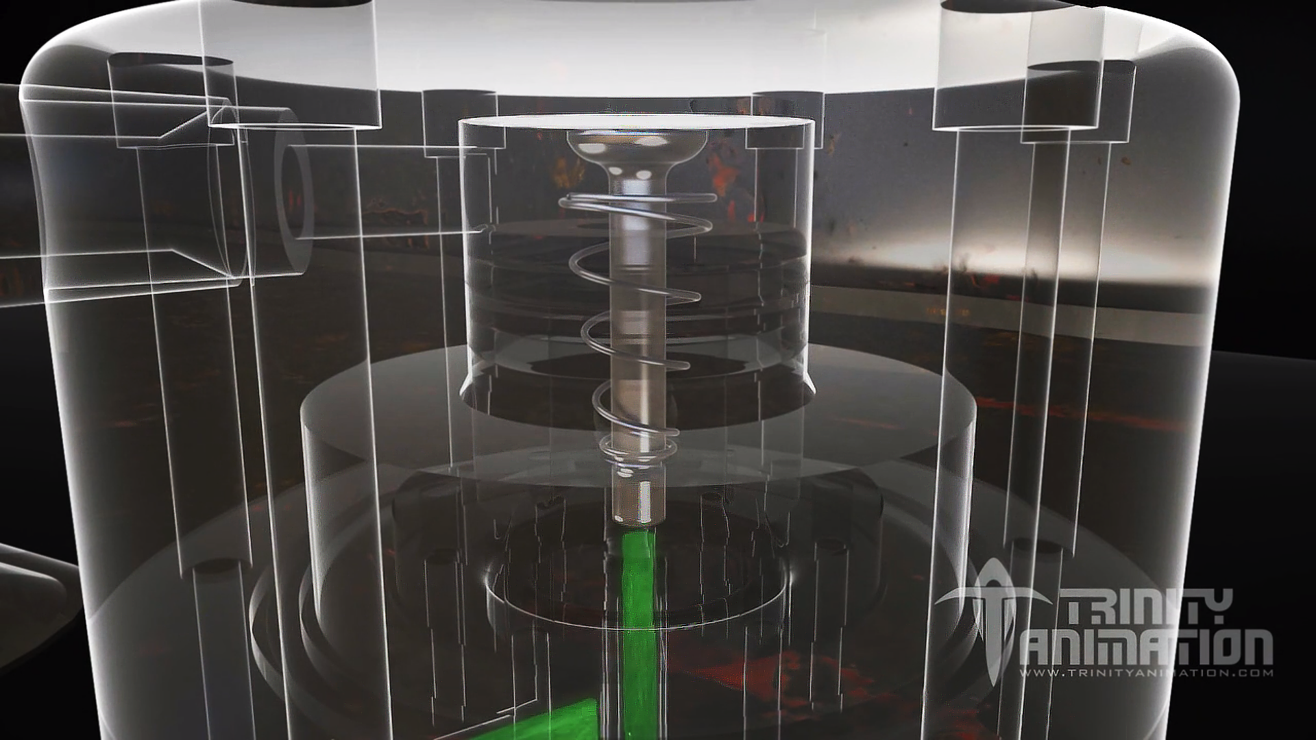
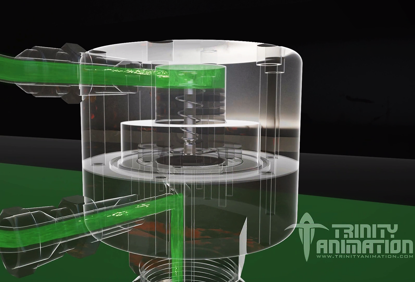
Trinity’s artists began work on this CAD animation with the original engineering data supplied by SpillX. They then ensured that all aspects of the CAD animation are drawn to scale and with features of the device accurately depicted. Trinity’s artists not only correctly represented the solid components of the system, but, they also used advanced animation software to show the actual viscosity and fluid streams of locomotive diesel fuel.  The result is a CAD animation that faithfully reproduces the key features of the of the fueling system, to scale, with precisely depicted materials and realistic fluid flows.  Trinity’s experience in bringing routine CAD animations to vivid life can help the manufacturers of many industrial products explain and promote their ideas to their customer base.

This is a 3D rendered image from Trinity's cad animation demonstrates how the StillX fuel system operates. This image displays a close-up dynamic angle of the receiver. The second fuel stream is being diverted through a piston in the lower house of the receiver. The fuel is represented as a green liquid and the components are transparent so the viewer can see the fuel flowing through the the parts.
Trinity animators are able to provide unique imagery and dynamic angles of these components through the CAD animation that viewers couldn’t get in person or through photographs. This image displays the second fuel stream being diverted through a piston in the lower house of the receiver.